Unfortunately (and not whilst working on the boat) Dave has had an accident.
He will be off for about 3 months and we have suspended the build.
Get well soon Dave.
Wednesday, 16 November 2011
BIlges painted.

A coat of gloss in the bilge and 6" up the cabin side will help keep the bilge easy to clean and resist corrosion although it is unlikely ever to be seen after the floor goes down.
Prior to painting the plate was brushed and vacuum cleaned paying close attention the the scuppers.
(ie the drain holes at either end of the knees)

Looking back over the fuel tank toward the stern.

The back cabin range will be installed at the port stern end of the counter plate so, because of the heat, this are will not be spray foamed. It has therefore been painted.
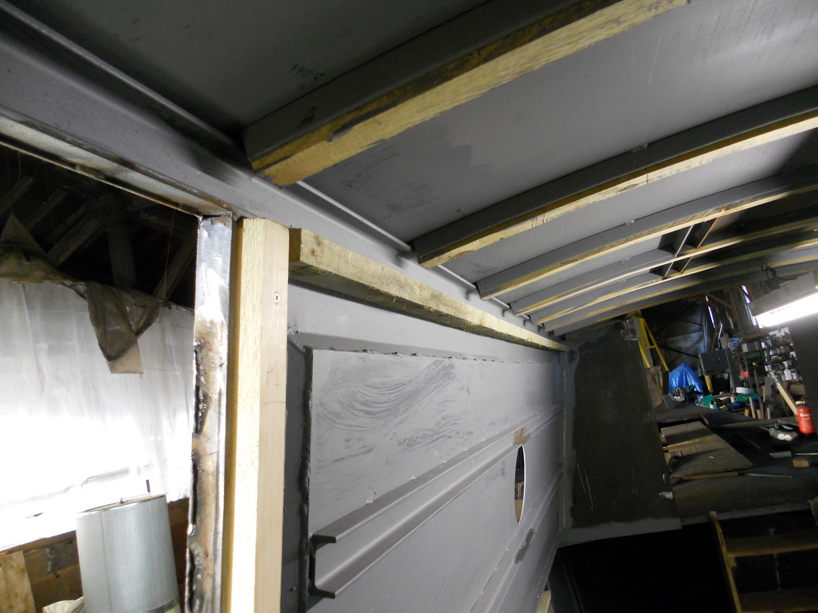
Roof details


Back cabin battening


Here is the battening in the back cabin. The photos are taken looking sternwards.
Those toward the front of the boat have cut outs to span the stiffening stringers which are installed in the straight panel sections. Where the panel is curved at the stern end of the cabin, the curve in the sheet stops the panel buckling. Therefore the stiffeners are not needed and consequently the battens need no cut outs.
The battens are self tapped into small tags welded on in advance . The battens were also Gorilla glued.
The photo below shows the tags along the edges of the inset panels before the battens were mounted.

Thursday, 3 November 2011
Battening the cabin sides
The cabin battening is installed by drilling holes at 12 inch centres along the bottom edge of the cabin top corner channel where the batten is affixed using self tappers through the batten into the steel.

Between the inset panels.

This is the batten fixed to the underside of the gunnel at 12-15 inch centres.
Obviously it has a sloped profile to allow the lining to follow the cabin side tumblehome.

As stated elsewhere the battens were all screwed and Gorilla-glued in place. The glue was applied quite generously to ensure enough was used to get a good area bonded. This photo shows the glue expanded out of the join during setting.
The skin fitting just welded onto to hull side is for the commoned up Kabola c/h and engine overflows to vent from the boat.
Battening under the front deck

As Dave is nearing completion of the steelwork I have been able to go down and get a couple of days work battening out prior to sprayfoaming. The first place I did was under the front deck where the foremost 3 of 6 battens can be seen. They are partially cut through to allow them to bend if required then held in place with screws through holes already drilled in the steel cross members.
To the right of the photo is the stainless steel domestic water tank which has been pulled back to allow fitting of the foremost batten. It will eventually be permanently installed up tight against the gas locker wall to the front of the deck hatch.
Notice that the gas locker floor is 12mm plate. That should contribute to the bow strength, stand some hard use and not rot through in my lifetime
For information.
The battens, in this case tannelised roofing lats, are installed before the hull is insulated.
These wooden ribs are installed right through the boat to allow the wooden interior of the boat to be fixed/mounted in place
Joins in the roof.
Ideally a 44 ft roof would be fitted as a single sheet to avoid seams with their associated risk of weld distortion at the joins.
Unfortunately 44 ft sections of decoiled sheet are not available so the roof was divided into 3 sections with the two roof joins being elegantly dealt with as follows.
The sternmost joint was put above the engine room . Here the compound curve of the roof sheer and lateral camber in this area can be facilitated by the inclusion of the removable panel which also leaves only a short section of welded seam to show at each side between the removable panel and the handrail.
(This is described in a previous post).
The foremost joint was arranged to come half way along the roof and hidden by a strap with centre rope rings at each end. On a wooden cabin this would have been bolted on so Dave has included a few bolt heads. Consequently a useful and decorative feature has been created.
This is seen on the photos below.


Port cabin sides now inset -2

Stages of welding can be seen on panel 2 as follows:
To avoid heat distortion the edges are carefully welded in alternate short sections of 2-3 inches, the alterante sections being allowed to cool before filling in. This shows on the vertical edges which have not yet been gound flush.
Along the bottom edge the weld has now been ground flush to give a crisp edge.
Dave did worry that these panels might suffer from heat distortion but in the end managed to get them all in absolutely flat.
Subscribe to:
Posts (Atom)