Wednesday, 24 August 2011
Holiday break
Build will be suspended from 20 August until 12 September while Dave has a well earned rest.
Thursday, 18 August 2011
Ian Kemp's back cabin rebuild
Now pay attention if you are interested in the construcion of a traditional back cabin.
This is the work of Ian Kemp who lets me see his work in progress and freely gives tips and comments. This is roughly equivalent to Michelangelo telling you how to paint the ceiling.
At this stage the cabin is almost complete and undercoated ready for graining and decoration.
Being a scumbaholic I am looking forward to seeing this stage of the process.
Although the colour seems to vary it is due to the camera and light conditions. It is a uniform creamy primrose colour throughout.

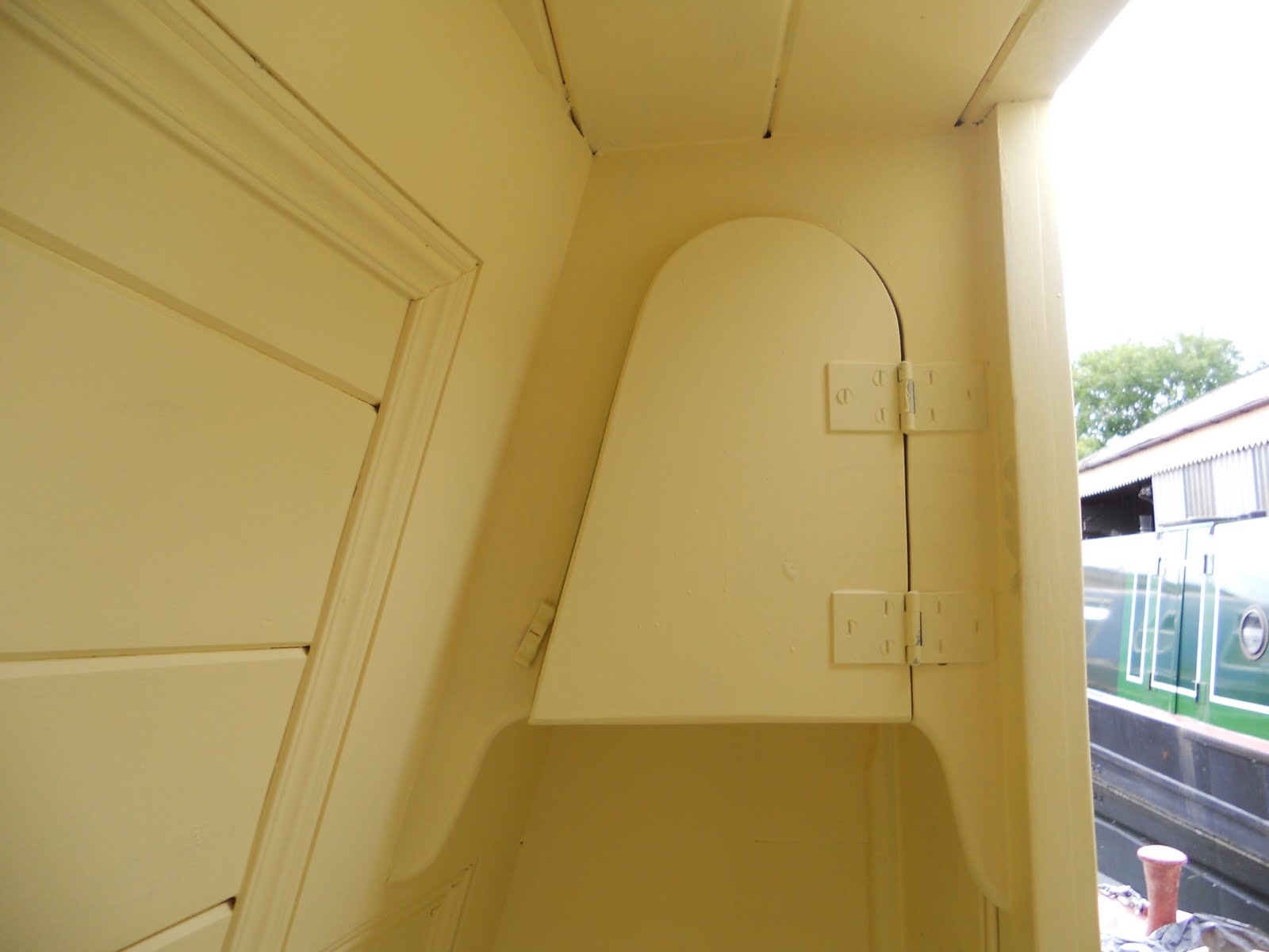
Here's the door from the back cabin to the engine room with a sliding cover over the decorated ventilation hole.
It reminds me of the upstairs back room of the Mason's Arms pub I where I went as a schoolboy to the Doncaster Wheelers meetings. The room was also used by the Buffalo's secret society and the door had a little peep hole so the members could see who was outside the door.
The hole top left is for an engine control rod of course.

Table cupboard and "crumb drawer" aperture.

Bed 'ole and baby drawer aperture beneath.
I had the impression that cabin floors were usually red oxide but Ian prefers a painted edge and scrubbed removable centre panel.

Access to storage below the bench and bed end is from from both above and the front.
The corner cut out is where the bed flap will "land" when deployed.

Soap and windlass 'oles and ticket drawer position above


Here are the absent components removed for gloss painting away from the cabin.
Stern interior cleaned and painted.


Whenever I visit I like to do any cleaning and painting possible as it's a relatively boring and unskilled job and Dave is better employed on the skilled work.
As a bonus, whilst focussing on this work I notice design and construction detail which I could otherwise overlook.
The access covers have been left bare as they will require further work.
The bare patch in the prop shaft "notch" is unintentional due to being gormless.
Cabin roof framing

Looking forward from next to the back cabin the roof and initial cabin framing are seen.
An unexpected bonus of this stage of construction is the convenient access almost anywhere on the boat gained by grabbing the roof edge and swinging up onto the gunnel then into the boat.
This results in a clean, shiny gunnel and jeans with a black backside.

I like this photo. Although the perspective slightly distorts the view, it gives the first impression of how the complete boat will look. The panel layout and saloon and engine room door positions can now be seen.

Looking along the roof from the back.
After some debate over whether the engine was ever likely to come out through the roof by crane we have decided to have a removable roof panel. Although the the engine is small enough (with some ancilliary parts removed) and light enough to remove via the doors, the panel has an important atribute:
- The roof is cambered by about 2 1/4" transversely and also cambered in the opposite direction due to the longitudinal sheer of the roof. This reverse compound curve would be very difficult to make in a single sheet without producing an unwanted flat. Introducing a roof panel allows this difficult problem to be solved as effectively 3 narrower parallel strips/segments are used.
The roof panel will be continuously lined over internaly as though it was not there.
If ever used it will be removed and a jigsaw through the lining run around the inside of the hole.

Front cabin bulkhead

Front bulkhead grooved to replicate planks.
The hatch is 25 1/2" wide and will be 24 1/2" wide when lined. This will allow most standard sized domestic items to be loaded through.


This shows the hatch and slide framing.
The framing is 25 x 50 x 5mm channel and has been drilled and countersunk to accept the wooden battens which will support the cabin lining.
Apologies for another photo of my foot. I am perched on top tof cabin framing looking through a camera and it's a long way to fall with plenty to hit on the way down.
Stern cabin bulkhead


Engine partially installed

Having almost completed the engine beds (see previous post on this) the engine was lifted into place with the mounting pads bolted to the sub frames. These were tacked in place and the engine lifted out again.
After the four pads had been finally welded in position the engine room was primered and under the engine, where access is limited, painted with raddle red. The engine was then put back in place as seen here.

This is the front view of the engine. For ease of handling and slinging during installation the alternator, drive belt and guard have been removed.

Top view of the engine. The gearbox flange face is 15 3/4" forward of the fuel tank front.
This engine position in the 7'6" engine room leaves usefull room forward of the engine and just enough room sternwards for the central access from the back cabin. However a split double bottom of the door will be needed for full opening.

The engine room will be entered on the port side so the 12mm bulkhead bottom has been cut down here to 3" (equal to the floor knee height) to allow a continuous floor and easier access to the space forward of the engine.
A hole has been cut for threading cables or hoses if required later.
Stern gear installation and fuel tank

Above is the stern tube welded into the hull. It is threaded internally to accept a bronze bushing bored to a slightly larger diameter than the prop shaft.
Click on the photo to enlarge it and the threaded internal bore into which the bush is screwed can be seen.
The bush is sealed in place but may be removed for replacement if required eventually after several years wear.

This is the internal view of the stern tube. Forward of this is a plate drilled to carry the stuffing box which is effectively a gland through which the 2" diameter propeller shaft exits the hull. The stuffing box contains a greased rope gasket wrapped round the prop shaft and compressed to form a tight seal which keeps the water out.
A grease injection system (the stern greaser) will be added later.

Further forward of the stern bearing is this plate which is drilled ready to accept the front/inboard bearing of the 5 ft long propshaft.( Forward of this bearing the propshaft will terminate at a flange which will couple to a cardan shaft with universal joints at each end. The cardan shaft will continue forward to the gearbox.)
This plate is made from 12mm baseplate offcut.
The top of the plate has a flat surface 16 1/4" above the baseplate which will carry the floor in the back cabin.

Turning 180 degrees from the front bearing and now looking forward the fuel tank can be seen.
The cardan shaft will pass through the "notch" in the fuel tank and couple up to the gearbox seen beyond.

The 100 gallon fuel tank, which has been pressure tested to ensure it's integrity has these two removable plates installed to give access to each side of the tank should cleaning, gauge fitting or other modificaton be required. The main feed tappings are for the engine and the Kabola diesel fired central heating boiler.
A breather and balance pipe beween the two upper tank halves will be installed.

The tapping for the diesel filler is on the port side under the back cabin floor. It is angled forward to allow the fuel filler to be forward of a welded joint in the gunnel (good practice) and adjacent to the engine room where a valve will be installed to allow tank isolation. The valve is intended to stop fuel theft.
Build accuracy: DH surpasses a well known aircraft maker.
On Friday 12 August I recieved a phone call from Neil E who had been at the yard to collect nb Lodestar after some paintwork by John . He had been watching Dave at work measuring up prior to fitting the cabin framing and could hardly believe that Dave was remeasuring and remarking because a 1/16" error had crept in on a 44'6" cabin.
Wondering if this was true, as Neil E is a winder upper, I have since asked Dave if actually did this. He admitted that he did contending that it is easier to get this spot on than deal with a 1/16" error later.
An engineer from the aircraft industry who has worked on the Boeing 747 commented even a 747 may vary in length by almost a foot.
Subscribe to:
Posts (Atom)