This week the electrics have been connected to the 12V and 240V panels in the engine room and the heavy current wiring of the batteries, engine and alternator. This was carried out by the electrician from Loom-tech.
Dave has continued building the back cabin which is now close to completion.
I have, as usual, done lots of small tidying up jobs and filled and painted which doesn't look much but regularly keeps me busy till after 10 pm.
The saloon stove is now bolted down on it's hearth awaiting the installation of the insulated flue and roof collar etc which will be carried out next week.
Also scheduled for next week are starting the engine commissioning and the plumbing.
Sunday, 29 July 2012
Saturday, 28 July 2012
Door liners fitted to doors - and painted yet again.
As described earlier the steel doors have wooden liners of traditional design.
The doors have been painted with primer and gloss before the liners, also painted the same way on their back face, were screwed on with marine sealant around the edges.
When this had set, the excess bead which had exuded from between the two was carefully trimmed off and the liners, which are exposed to weather when the doors are open, painted with thinned paint to penentrate the wood. The six pairs of doors have now been remounted onto the hull and will also receive a coat of gloss before eventual undercoating, graining and traditional decoration

Under tug deck painted
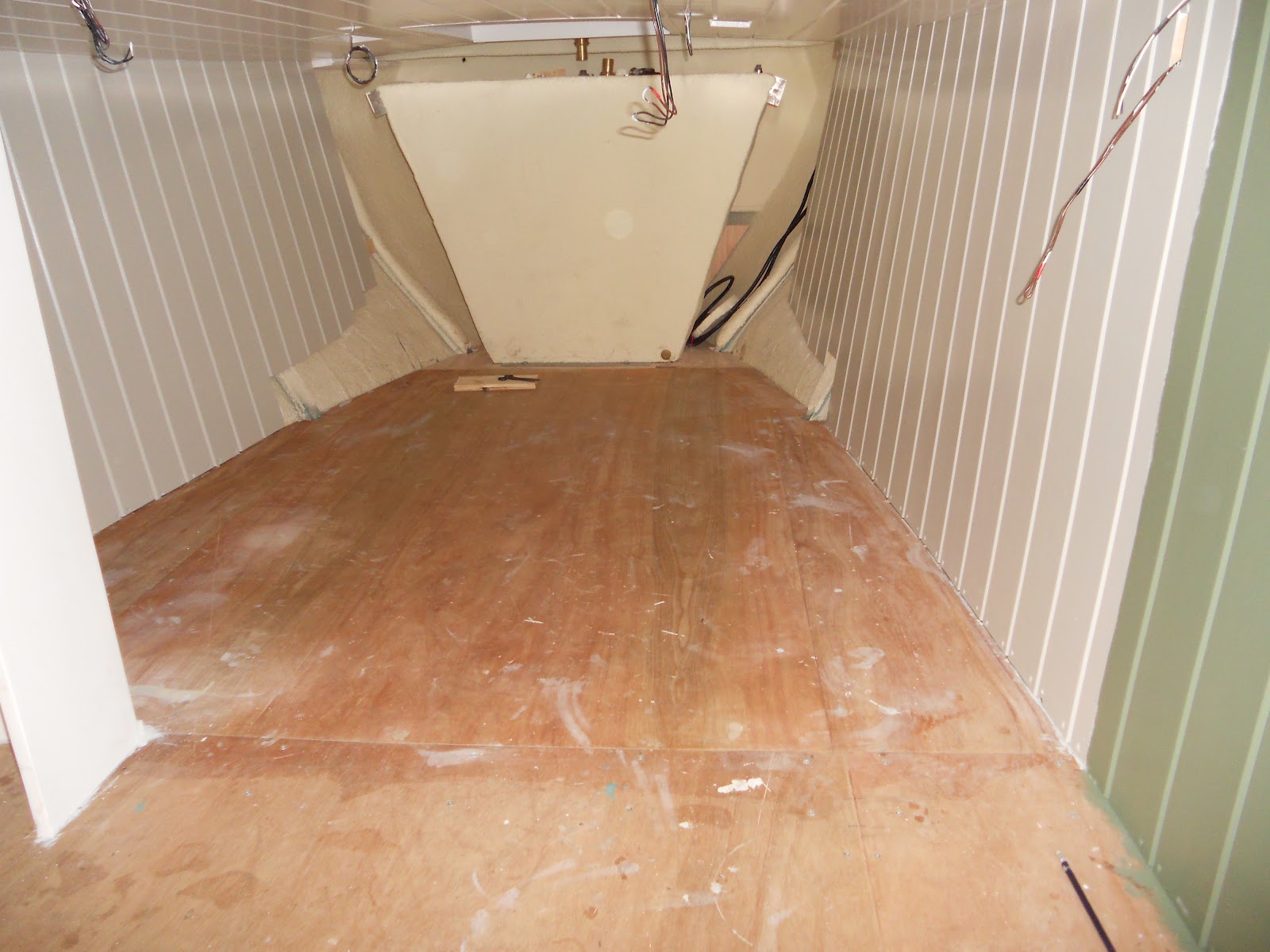
Under the tug deck the hull sides have been painted a pale grey /green as carrying the sage green in the saloon right through here would have made the area a bit too dark. The board on which the colour change takes place will be covered by the curtain when drawn back.


This is the view from under the tug deck into the saloon.

This is the view from under the tug deck into the saloon.
Engine controls
The engine controls will be of traditional design with steel rods routed from controls at the steering position, along the back cabin ceiling to the engine throttle and gearbox.
The gears are to be changed by a push/pull handle on the starboard side and a "speed wheel" for the engine throttle on the port side.
Below is the rear bearing which will carry the rotating shaft of the speedwheel throttle control.
It is bolted solidly to the cabin roof as this shaft is sometimes swung on as the cabin is entered.

Further along the cabin ceiling the throttle control shaft will through a small hole drilled in the cabin framing.
We noticed that the shaft would pass directly under a light positioned over the table cupboard so this was adjusted by filling in the hole intended for the light with a blank which can be seen just left of the roof prism frame. The light has been moved a few inches left where the wire can now be seen hanging out of it's ceiling hole. Hardly a gross error and it will be easy to hide when painting proceeds.

At the front end of the engine speed control shaft is this worm drive which will convert the rotational shaft movement to a vertical push and pull.. It is mounted directly over the engine speed lever on the governor.

Back cabin - starboard side
Panelling has been framed and the decorative trim mimicing the framing of a wooden cabin is being added.

The stern starboard side of the cabin has a useful space used by, from top down:
-Switch panel for tunnel light, horn, bilge pump, cabin light and 12V power point.
-Small cupboard with traditional round topped door.
-(Yet another) shelf.
-Bench end sloping topped storage box. (Is this called a monkey box?)
-

Back cabin - cross bed and cupboards above
Good progress has been made this week on the back cabin.
Below is the cross bed shown in folded down across the cabin - ie deployed for use.
The centre section of the bed base is formed by the cupboard front being dropped down across the cabin to "land" on the bench on the starboard side.


Here is the view looking backwards along the starboard side.
The bench on which the bed flap "lands" can be seen in the foreground.
Obviously the dimensions of the bed flap, bench and central gap must be carefully matched for this to work and stow neatly.
In this case the bed has been built slightly wider at 4 feet and lower to give increased head and foot room under the gunnels. This has resulted in a step in the bench base however it is envisaged that one of the other bed base cushions (central or port side) will be used on top of the starbaord side cushion (when the bed is stowed in the day) to give a level top when noit used as a bed.


Below is the cross bed shown in folded down across the cabin - ie deployed for use.
The centre section of the bed base is formed by the cupboard front being dropped down across the cabin to "land" on the bench on the starboard side.

Here it is shown slightly beyond it's (vertical) stowed "up" position.
Drawers will be installed in the space eblow.

Here is the view looking backwards along the starboard side.
The bench on which the bed flap "lands" can be seen in the foreground.
Obviously the dimensions of the bed flap, bench and central gap must be carefully matched for this to work and stow neatly.
In this case the bed has been built slightly wider at 4 feet and lower to give increased head and foot room under the gunnels. This has resulted in a step in the bench base however it is envisaged that one of the other bed base cushions (central or port side) will be used on top of the starbaord side cushion (when the bed is stowed in the day) to give a level top when noit used as a bed.

Below is the cupboard above the bed box which has provision for an extra shelf to be slid into place.
This is because in use shelf area has been found more important than volume alone.
ie a pile of kit/clothing of full cupboard height falls over

Slides clad with stainless steel sheet

As described in an earlier post the slides for the front, back and engine room hatches are made from ply with iroko side runners. The slides have been skinned with 1.2mm stainless steel for strength and to protect the end grain of the ply. This was carried out at a small local sheet metal shop.
In the local area there are fortunately still many small specialist machining, general engineering and artisan businesses which are usefull to a boat builder.
The corners have been welded and the back edge shaped closely to follow the tapered iroko runner.


Friday, 20 July 2012
Back cabin - table cupboard
The focal centre of a back cabin is the table cupboard shown here in the early stages of construction.
Note that to conform to the spirit of the new fire regulations the table cupboard has been built with an airgap and fireboard (to be added) to the left hand side, adjacent the range.

At the bottom is the small trapezoidal (in plan) cupboard utilising the space against the swim and above this is the "crumb drawer," so called because it collects crumbs when the table above is stowed.
It is actually used for storing cutlery.

Below is the table cupboard with shelves within and a smaller cupboard to use the space above.

Here is the cupboard front which when installed doubles as a drop down table.

Saloon fireplace
The fireback has been ceramic tiled over the "super isol". Both it and the quarry tile hearth have been grouted.
I was not satisfied with the finish of the paint on the hull side as the texture of some knotting was showing . The panelling has been rubbed down again and bare patches re primered.

I was not satisfied with the finish of the paint on the hull side as the texture of some knotting was showing . The panelling has been rubbed down again and bare patches re primered.

Electrical installation
This is the Loom-tech electrical panel for both 240 and 12 V systems connected up and about to be screwed in place at the rear of the engine room.
Above the panel the Victron battery monitor has been installed.

A view into the electrical cupboard just before the panel is placed shows the 12V neg bus (top R) and the 12V "power post", both being Blue Seas products.
This panel must be screwed in place rather than accessed through an opening door as 240V is present.

Below the electrical cupboard are mounted:
Victron 30A battery charger (blue)
Galvanic isolator, to the left of the charger
Shore lead inlet , cabin side above the GI
2kW Ring inverter, below the charger
This region has been left uncovered to aid cooling and access.
The engine and domestic battery isolation switches, again by Blue Seas, are the two red objects mounted on the hull side. They have yet to be connected as have the batteries in the green box below.


Swan's panel painted by Ian Kemp
As promised last week here is a picture of one of the cabin panels on Swan painted by Ian Kemp.


Saturday, 14 July 2012
Engine coolant pipe
The 28mm engine coolant pipe from the thermostat housing to the skin tank has been run about 4" below the gunnel where it is out of harms way and will form a convenient drying rail.
Now the electrical cupboard has been painted the diesel tank breather and battery vent pipe have been reinstalled running up the corner.
Since the photo was taken the battery box has been gloss painted internally.
![]()
Now the electrical cupboard has been painted the diesel tank breather and battery vent pipe have been reinstalled running up the corner.
Since the photo was taken the battery box has been gloss painted internally.

Door liners
Here a wooden door liner of traditional design is being made.

Rather than use an external padlock and hasp (which can be inconvenient to use) Dave has cut into the lining to install a mortice lock which can be used from inside or outside of the boat.

Here are the completed door liners which will be traditionally decorated.
The keyhole shows at the top of the LH door.

Saloon decoration continued. +Paint (in)decision.
The saloon hull sides have been painted eggshell sage green, a victorian "heritage" colour.
The cabin sides are to be painted a complimentary eggshell slaked lime (off white) with a slightly darker framing.
The ceiling will also be repainted in the slaked lime off white
Paint colours:
I have previously painted the ceiling and part of the engine room in ivory gloss which appeared a bit to stark - like brilliant white and not in keeping with the boat. Later on the bedroom and under the deck I experimented with a cream which appeared OK outside but too yellow/lemon in place although this could be put down to the flourescent lighting presently used in the boat.
This will all be repainted in off white eggshell which has wasted a few hours.
The problem is that the boat is currently in a dark shed and lit by very harsh internal lighting which makes colour choice , especially of the subtle pale colours, quite difficult. I have consequently decided to choose colours off the card as best possible but be prepared to redecorate after some time in actual daylight conditions.

The stove has been drilled, tapped and bolted down to the hearth but was later removed to carry out the tiling which was completed on Friday.


Front door surround and step
The front door surround, step and port bulkhead have been built.
-Since this photo was taken they have also been filled and painted as far as the undercoat.
The step is of iroko and will be fitted with a brass tread plate later after the doors are lined.
The wire protruding from the hole is where the saloon light switch will be fitted. This puts it in a convenient position to operate when entering a dark boat.
The bulkhead has been left clear at present although some shelves could be added later.
The ceiling has been painted with ivory gloss although a decision has been made to change this to eggshell.
![]()
-Since this photo was taken they have also been filled and painted as far as the undercoat.
The step is of iroko and will be fitted with a brass tread plate later after the doors are lined.
The wire protruding from the hole is where the saloon light switch will be fitted. This puts it in a convenient position to operate when entering a dark boat.
The bulkhead has been left clear at present although some shelves could be added later.
The ceiling has been painted with ivory gloss although a decision has been made to change this to eggshell.

Sunday, 8 July 2012
Work to 6 th July.
Apart from the work described in the previous six posts which mainly reflects Dave's efforts, I have been finishing sanding and painting.
Most of the ceiling right through, except for the back cabin has now been primered and undercoated.
The ceiling has received it's first top coat of ivory gloss as has the engine room cupboards and panels which are planned to be grained.
Painting which does not involve a change of colour doesn't show on photos so I have not included any.
As of Friday night Dave was making the hatch slides and I was painting ceilings - and myself.
We are still making good progress.
Saturday, 7 July 2012
Back cabin range installation
Back cabin ranges are, by virtue of their small firegrate area, exempt from the new stove regulations.
(I don't think there has been a back cabin stove fatality in 200 years of their use)
However for safety and in case of stricter future rules we have decided make best efforts to comply with best practice where reasonably practicable.

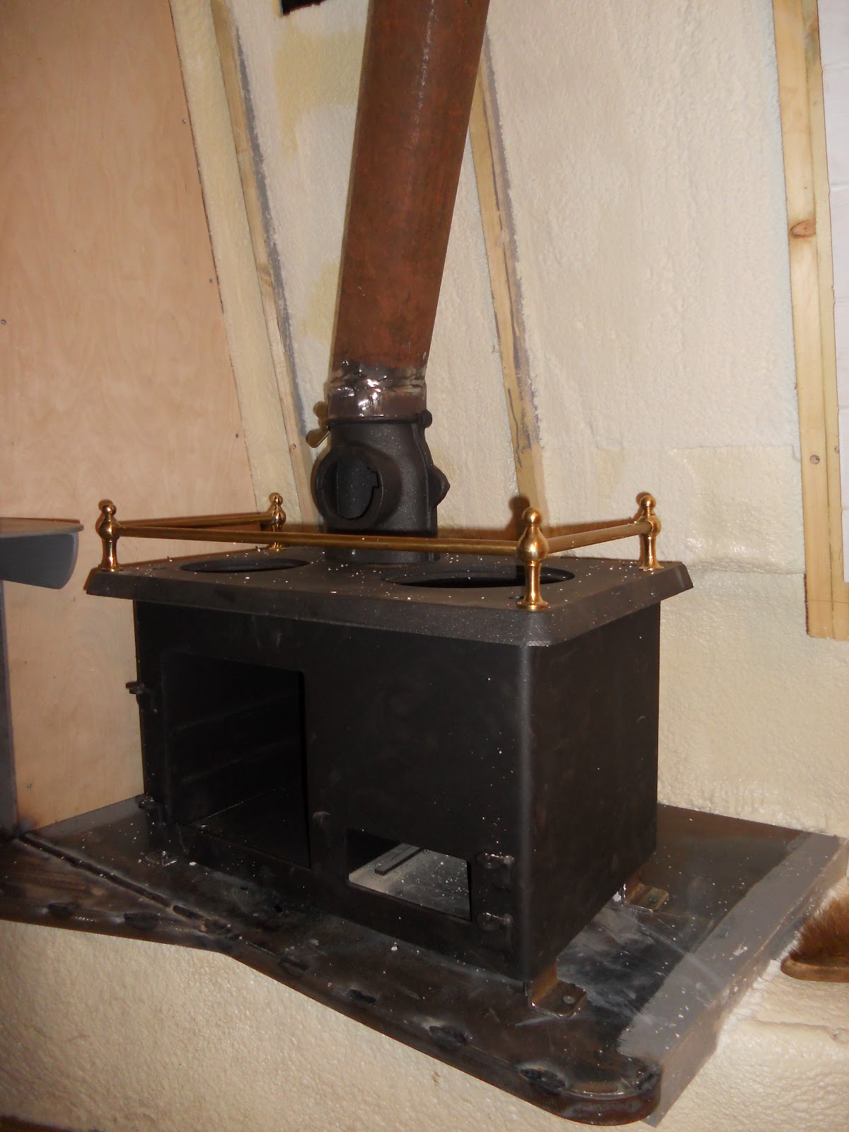
Here the stove has been lifted into place on it's steel hearth.
The supplied legs which were about 6" long have been discarded in favour of 2" legs which lower the range and give the stove and flue more clearance to the cabin side
There is an additional 2" gap to the swim base plate and nothing combustible directly below.
Here is a 4 1/2" (110mm) spacer cut from a convenient piece of scrap wood.
In subsequent photos it is shown demonstrating clearance to:

-The back RH side of the stove:

-The back LH side of the stove

The smoke box / flue bottom.

- The flue top near the chimney collar.

Note that depite being fire retardant, the insulation has been cut back to 1/2" thick to give an increased air gap between the insulation foam and the (yet to be installed) fire board.

The flue is held tightly by the three bolts drilled and tapped through the chimney collar.
It will thus be suspended by these bolts taking it's weight rather than carried by the stove firebox.
This lower joint, which will be free to move slightly to take up thermal movement, will be sealed by ceramic string .
 A small triangular fillet has been added at the LH front side of the hearth to protect the wooden swim lining boarding to be installed below.
(I don't think there has been a back cabin stove fatality in 200 years of their use)
However for safety and in case of stricter future rules we have decided make best efforts to comply with best practice where reasonably practicable.

Here the stove has been lifted into place on it's steel hearth.
The supplied legs which were about 6" long have been discarded in favour of 2" legs which lower the range and give the stove and flue more clearance to the cabin side
There is an additional 2" gap to the swim base plate and nothing combustible directly below.
Here is a 4 1/2" (110mm) spacer cut from a convenient piece of scrap wood.
In subsequent photos it is shown demonstrating clearance to:

-The back RH side of the stove:

-The back LH side of the stove

The smoke box / flue bottom.


Note that depite being fire retardant, the insulation has been cut back to 1/2" thick to give an increased air gap between the insulation foam and the (yet to be installed) fire board.

The flue is held tightly by the three bolts drilled and tapped through the chimney collar.
It will thus be suspended by these bolts taking it's weight rather than carried by the stove firebox.
This lower joint, which will be free to move slightly to take up thermal movement, will be sealed by ceramic string .
Engine exhaust
The silencer has been mounted to the roof fitting and Dave has constructed this tidy exhaust incorporating in 2" BSP from engine upwards:
Hand made flange to engine manifold.
Large radius bend. ( cheap from the farm shop)
Two couplings welded together to get the correct length.
Flexible section to allow a small bend and vibration in use.
Union to silencer bottom.
Yes the silencer coupling is slighly cockeyed but it will eventually be wrapped in insulating tape to protect against burns if touched.


Engine room pigeon box
Here is the engine room pigeon box.
Rather than the more common pitched roof type (which are more prone to water ingress) it is of the flat topped FMC shape.

Rather than the more common pitched roof type (which are more prone to water ingress) it is of the flat topped FMC shape.

Cardan shaft containment
This photo shows the access hatches for the fuel tanks. The covers have been removed for the dipsticks and fuel pick up pipes and valves to be installed.
The vapour balance pipe spanning the two sides of the tank provides a means of restraint for the front end of the cardan shaft in the (very unlikely) event of it coming loose.

Given regular checking of the coupling bolts, unplanned detachment of the shaft is highly unlikely.
However a heavy 8 foot shaft waving around at 400 RPM could cause serious damage so at this convenient time, a containment ring was constructed near the aft end. It can be split easily at the two bolts either side to allow removal of the shaft.

Engine and C/H header tanks
Header tanks have been made for the engine cooling system and C/H system.
They are constructed from 4mm steel plate.
The engine header which will be painted grey will be mounted in view on the wall directly ahead of the engine.

The C/H header will be mounted in the cupboard above the Kabola adjacent the flue.

They are constructed from 4mm steel plate.
The engine header which will be painted grey will be mounted in view on the wall directly ahead of the engine.

The C/H header will be mounted in the cupboard above the Kabola adjacent the flue.

Saloon stove surround
To meet the newer and more demanding regulations for solid fuel stove installation the fire backboard is of 25mm thick "Super Isol". This material is so fire resistant and has such low thermal conductivity that it can be touched comfortably on one side whilst a gas flame is played on the other. Behind it there is a 1.1/2" (37mm) airgap to the nearest "combustible material" which is fire retardent insulating foam.

The Super Isol which is quite soft will be ceramic tiled. It has been treated with PVA to aid tile adhesion.
It is protected at the edges (outside the hot zone) by wooden profile pieces
.


The Super Isol which is quite soft will be ceramic tiled. It has been treated with PVA to aid tile adhesion.
It is protected at the edges (outside the hot zone) by wooden profile pieces
.

Subscribe to:
Posts (Atom)