Last week the engine was test run for a day although a small air leak into the fuel line between the tank and engine lift pump means the engine stops after 2 hours (exactly). The engine easily restarts after bleeding the air from the top filter housing.
Over the next week the connections in the fuel line and primary filter will all be remade and the return fuel route (which should self bleed the system) checked.
This will hopefully fix the problem.
Dave has continued making galley doors and is currently laying the oak floor.
I have, as usual, mainly been painting.
The central heating system was filled and after replacing a faulty drain valve (which would not close) and refitting the radiator valve connectors with LSX to seal the thread wher they screw into the rad, the system held water.
The boat is due at the shotblasters on 4th September so the maiden voyage is imminent.
Monday, 27 August 2012
Even more painting

We had the Monday bank holiday off so Dave worked Saturday fittting the oak floor and I brought home the cupboard doors and shelves from the back cabin and galley to paint at home over the weekend.
Below are 23 items in my garage. Each has to be painted on one side and the edges, carefully stacked, then after drying flipped over to paint the reverse.

Rustic oak planked floor
The floor is clad with solid oak planks 19mm thick.
The least expensive rustic grade was chosen as it was about half the price of the top grades and the variety of grain, knots and other imperfections are in keeping with the rest of the interior.
The sub floor was varnished first (in case of any water spillage) and the planks oiled on the underside and into the tongue and groove before fitting.
The oil used was Osmo - Polyx Oil which is £60 for 2.5 litres (!) but has been well proven on a friend's boat.
Dave fitted the planks starting from the port side with the first plank screwed down through it's top surface. This will be hidden under the skirting board.
Subsequent rows have been screwed invisibly through the tongue at an angle.
After fitting the top surface was oiled.
The finnished surface can be seen below.

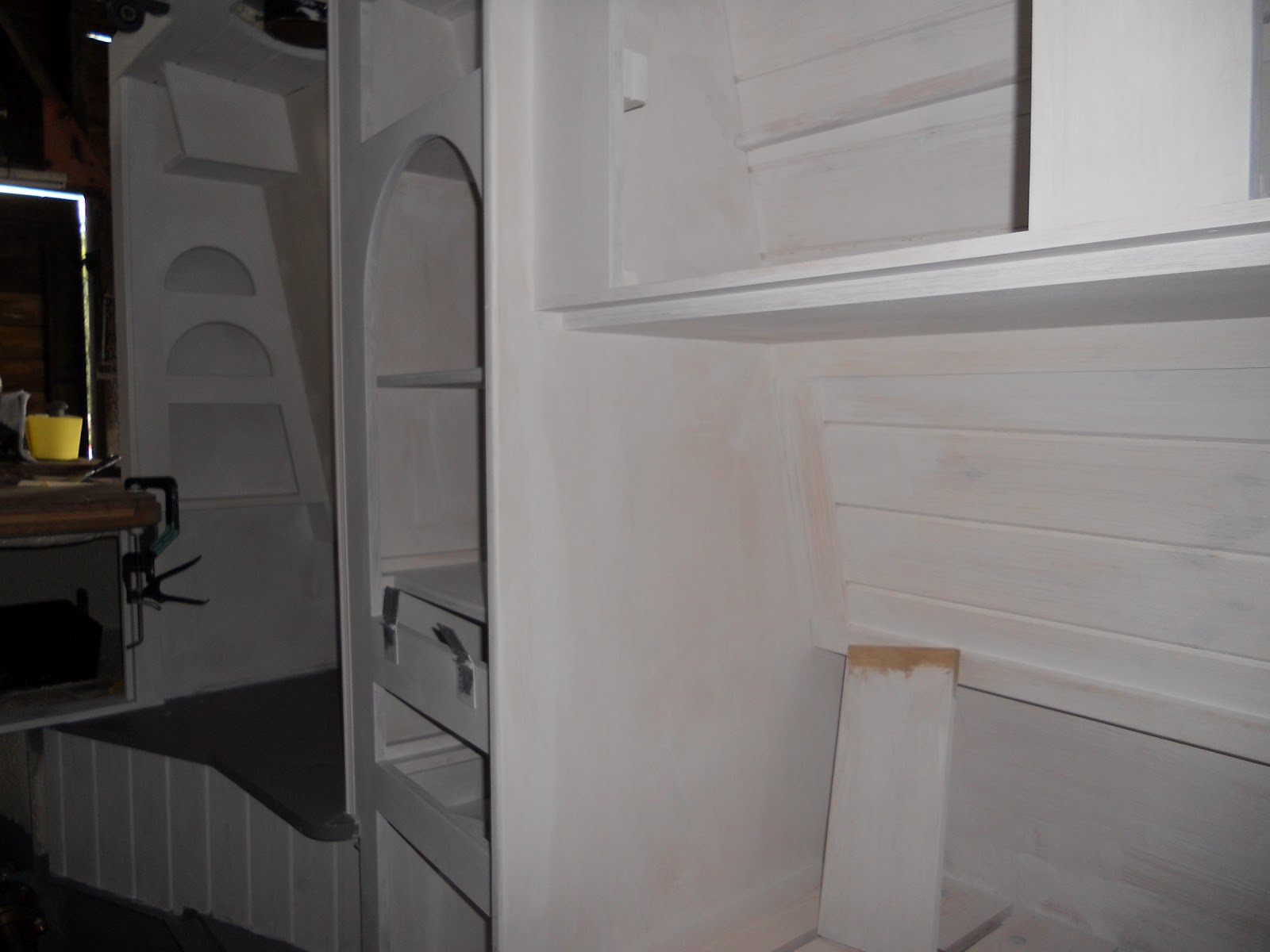
Galley carcases and worktops
Here the galley carcases have been built and the iroko worktop which has had two coats of danish oil temporarily put in place.
The carcases have received their first coat of paint which is much more easily carried out with the doors and worktop off.

The carcases have received their first coat of paint which is much more easily carried out with the doors and worktop off.

Saturday, 11 August 2012
Summary of work to 3rd August - Engine running!
Another milestone was passed this week when we started and ran the engine for the first time.
A rebuilt vintage engine is less predictable than a new one but so far I think I've got a good one.
The plumbing is well advanced with the C/H completed.
Dave has started building the galley.
Launch is next week.
Back cabin (more) beading and painting.
Beading has been added where appplicable to the panels, doors and drawer fronts ( most removed) in the back cabin before the remainder of the bare woodwork was primered.
Painting thoroughly inside the cupboards isn't much fun due to the restricted access.
The table cupboard shelves, drawer runners and internal faces can usually only be accessed and inspected by getting your head in through one hole (where it is often just above the fume laden paint pot) and arm in though another.
Once again I have painted myself in the process and noted that paint fumes are a poor substitute for beer when a hangover is required.


Plumbing. C/H and calorifier

The photos above and below show the pipework of the C/H and calorifier over which the bed will be built.
The back of Kabola boiler in the engine room can be seen through the (large for access and ease of use) gap in the bulkhead.
The vertical grey object is the Bolin circulating pump.
At this stage (whilst commisioning the engine) the engine heat exchange pipes have not been connected to the calorifier but have been bridged with the black rubber hose where they enter the bedroom.
The pipework has been designed and installed with ease of access optimised.
C/H pipes are generally 22mm copper and the domestic supply 15mm Hep2O.
The wider view below shows the small radiator which will be in the bedside wardrobe .
The valve which will shut off the C/H and route the hot water only to the calorifier is just to R of the radiator.

Two more radiators are installed in the saloon and under the tug deck.
Kuranda marine, the supplier of the Kabola boiler have recommended the connection of the rads as shown to the top side of the circuit (rather than bridging from flow to return).
Apparently it warms through just as well as the sytem gets hot. A side effect is that the boxing which we will build over over the pipes can be slimmer. The boxing will have a continuous slot along which heat can escape into the accomodation from the copper pipes.

Engine commissioning and start up.
As described in previous posts, the Gardner 3LW engine was built in November 1960 and rebuilt by Walsh's Engineering in 2009. It was delivered to the yard shortly thereafter and has since been in storage awaiting construction of the boat.
Dave put the engine into the boat during the build and we have since installed the shaft, stern gear and main cooling pipes to the skin tank leaving the final fuel piping and commissioning of the engine until now.
Now here's a bit of good luck....
Being a member of the Gardner Engine Forum (owners club) I noticed in the club magazine that Steve Gray, the editor of the club magazine lived half a mile from the yard so I made contact.
I was delighted to find that Steve, a second generation canal boat owner, professional engineer and vintage engine expert with a 3LW and astonishingly well equiped workshop would be available to help with the final aspects of installation of the fuel system and commissioning the engine.
The peace of mind and reassurance of finding an expert close at hand should not be underestimated.
In the last few days Steve completed the cooling pipework leading to the calorifier (see a couple of posts ago) and installed the fuel delivery pipework to the engine and also the Kabola.
Additionally Steve made another thermostat housing to match our cooling and calorifier routing and also the oil pressure gauge bracket seen in the photo below. This puts the gauge close to the engine oil pressure tapping but positions (and angles) the gauge where it can be conveniently seen from the steering position.
Also seen in the photo below are the filters for fuel to the engine (L) and Kabola C/H boiler, the red item at the front of the engine room (R). In use they will be under the fronrt floor panel.

Eventually the moment came to start the engine and with heart in mouth the button was pressed.
The engine fired instantly but died after a few seconds. This was on fuel which had remained in the engine from 3 years ago.
The problem was quickly identified as lack of new fuel and the lift pump which was not actually lifting fuel removed and rebuilt overnight by Steve.
No obvious problem was apparent but the pump had stood for three years without use.
This was refitted and the engine started readily and ran smoothly and with good oil pressure.
After half an hour the fumes in the shed became too acrid and we shut down.
Next day the engine refused to start, once again showing no fuel at the injector pump bleed off.
Steve changed the non return valve at the lift pump delivery side and this fixed the problem so the engine started and ran OK.
These valves are kept clean and in good condition by use and fuel flowing over them so this small bug is consistent with no use over the last 3 years.
Therefore I expect this problem to become less frequent as the engine is used having been shown what to do I will be able to quickly free the valve myself.
Saturday, 4 August 2012
Saloon stove - flue, roof collar and chimney installation
As previously mentioned, regulations covering the installation of solid fuel stoves in boats have recently become much more stringent. To meet these regs, pass future safety inspections and ensure the boat is as safe as possible much effort has been expended.
To recap, the stove is bolted down onto a hearth of quarry tiles cemented onto 12mm steel plate welded to the knees with nothing combustible beneath. The fireback is of ceramic tiles on 25 mm super-isol with an airgap behind to the fire resistant hull insulation and an airgap below and behind the stove exists. In addition the stove is CE marked.
Photos below show how the flue was installed.
Where the flue passes through the roof a 60mm annulus of insulation and cabin lining has been removed:

This annulus is then filled with aluminium oxide ceramic wool:

Which is retained by a stainless steel dress plate. For decorative purposes the dress plate has been engine turned although I might paint it to match the ceiling later:

The flue is made of stainless steel and double skinned, once again with the annulus filled with ceramic wool. The welding and subesquent finnishing have been well executed as seen on this bend.
The top of the flue can be seen here where it fits the through the chimney collar on the roof.
It has 4 bolts into it's end which pass through the large "washer" seen top right. When tightened up, these bolts carry the flue, supporting it in tension with a small expansion gap within the stove collar which is filled with ceramic wool topped off with a small protective layer of high temperature sealant.
Note also partially obscured is an eye bolt to which the stainless steel chimney (or if not in use the collar cap) are chained. The collar has been shimmed with a custom made tapered spacer to make it absolutely vertical on the sloping roof

The chimney is double skinned and very solid with square bar brass handles.

Here is the finished installation. Note that the flue has no adjustable components in it but follows the hull and cabin sides exactly as it was custom made after a preliminary site vist with a measuring jig.
The flue, collar, chimney other components were made and installation carried out by Roy Willoughby.
This cost more than the stove itself (gulp) but the quality easily justifies this.
Roy Willoughby can be contacted on 07580-970553.


Engine and C/H header tanks and overflow pipes

To keep the installation tidy the overflow pipe has been routed from the back of the tank through the cupboard.
To the right the cream header tank for the central heating system can just be seen.
This will later be hidden by a door in front. The (just seen) overflow pipe from this tank is commoned up to the engine overflow pipe and exits the hull at the fitting just below the gunnel in bthe far corner.
The pipe also commoned up to this is the vent pipe from the calorifier (over) pressure release valve.
Because the calorifier will be mounted lower down (undert the bed behind the wall) an inverted U has been included so the engine or c/h do not vent into this leg.
Back cabin - insulation of wall behind range

Behind the range position in the back cabin insulation has been removed and an airgap made behind the lining as shown.

The lining in this area is of fireproof cement board:

Which will later be tiled or painted, with water based non combustible paint.

Lamp stand / deck lid support
The tunnel lamp at the fore end will be carried on this sturdy steel stand which also serves as a stop to support the deck lid when it is opened.
I can forsee it also doing duty as a handy washing line support - the other ends of the line being secured to the cabin rings.

The base of the lamp stand is bolted secrely to the fore deck.
The lamp wires will pass up the inside of the stand to emerge from an oval hole just below the lamp bracket.
This will be sealed with silicone sealant.

Portholes- glass and installation.
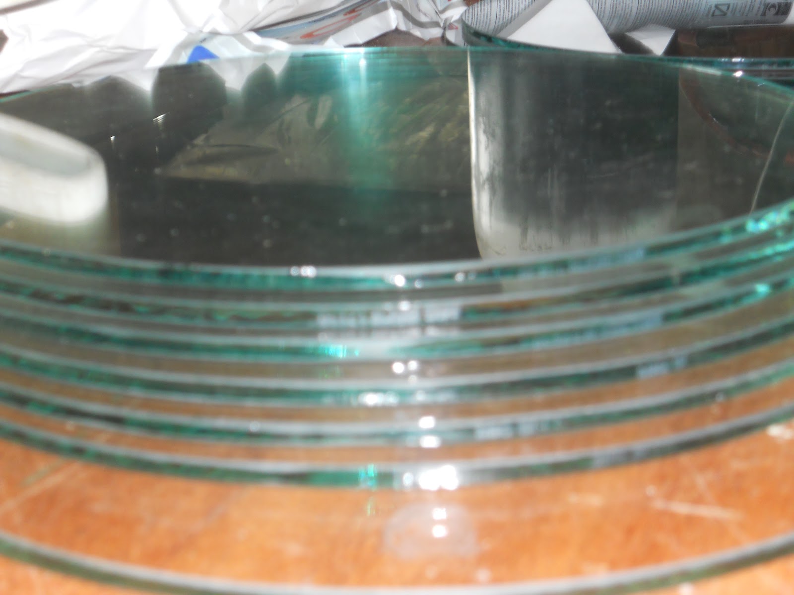
The porthole glass on boats must be of toughened glass and marked to the relavent British Standard.
Usually this results in a "kite mark" visible on the face of the glass.
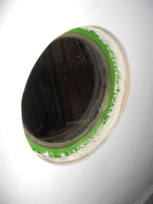
These glasses were supplied by Midland Industrial Glass and have been marked with the BSEN , not where it will be seen, but on or close to the glass rim where it will be hidden when installed. I have therfore photographed the glasses and obtained paperwork to prove their origin in future.
 The BSEN can just be seen on the edges of the glasses above and on the face edges of the glasses below.

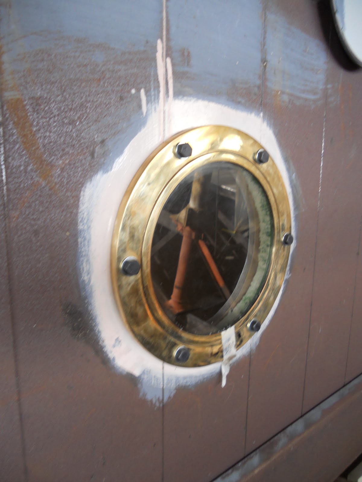
Here the glass has been stuck in place in the brass porthole with silicone sealant.
A gasket made of closed cell rubber window tap is then attached. The join is at the bottom of course.

The porthole is then bolted to the cabin although it will be removed for shot blasting.

This view shows the inside, painted to protect the steel against condensation although the wooden cabin porthole liner will be sealed against the glass with silicone sealant.
Usually this results in a "kite mark" visible on the face of the glass.
These glasses were supplied by Midland Industrial Glass and have been marked with the BSEN , not where it will be seen, but on or close to the glass rim where it will be hidden when installed. I have therfore photographed the glasses and obtained paperwork to prove their origin in future.

Here the glass has been stuck in place in the brass porthole with silicone sealant.
A gasket made of closed cell rubber window tap is then attached. The join is at the bottom of course.

The porthole is then bolted to the cabin although it will be removed for shot blasting.
This view shows the inside, painted to protect the steel against condensation although the wooden cabin porthole liner will be sealed against the glass with silicone sealant.

Subscribe to:
Posts (Atom)